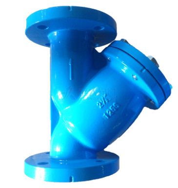
Standard for Hydraulic Control Valves

The hydraulic control valve is an important part of water conservancy engineering needs, related to the quality and safety of the project, hydraulic control valve is the pipeline itself medium pressure as a power source, open and close, regulation, the leading valve, and system small pipeline different combination, can have nearly 30 kinds of functions, now gradually get more universal use.
Pilot valves rely on as the control object of the water level and pressure changes and action, because the pilot valve type is many, can be used alone or in several combinations can make the main valve to achieve the water level and water pressure and flow, such as the function of separate or compound adjustment. However, the main valve is similar to the globe valve, when the valve is fully open, its pressure loss is much larger than other valves, and the closer the loss coefficient of each opening degree is to the full close, the greater the increase, the larger the valve diameter is more significant.
The valve with the above characteristics, in close to full closure, the action of the disc is accelerated, easy to send the water hammer (water impact pressure), close to full closure, the valve action is slower, the better, so can set throttle mechanism on the disc. In addition, the pilot valve throttling and action part should try to avoid setting a special small aperture, so as not to block. If necessary, add filter screen, periodical maintenance, and set up bypass pipeline. This kind of valve is promising for development and use.
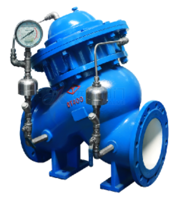
The hydraulic control valve is a water pressure control valve, it consists of the main valve and its attached pipe, pilot valve, needle valve, Stainless Steel Ball Valve, and pressure gauge.
Use of hydraulic control valves, the first to pay attention to the selection. Improper selection will cause water and air leakage phenomena. When selecting hydraulic control valve, the displacement of the hydraulic control valve must be selected by multiplying the equipment's steam consumption per hour by 2-3 times the maximum condensation water. In order to ensure that the hydraulic control valve can discharge condensate as soon as possible when driving, rapidly increase the temperature of the heating equipment. Hydraulic control valve discharge energy is not enough, will cause condensate can not be discharged in time, reduce the thermal efficiency of heating equipment.
How does it work?
Flow-control valves in hydraulic systems are generally used to regulate the pressure in the flow rate of either gases or liquids as they travel through a pipeline.
Flow-control valves are extremely important for optimizing the performance of the system, so choosing the right valve for the job is likewise crucial: a flow-control valve manages the flow rate in any given portion of a system of hydraulic circuitry.
Within a hydraulic system, a flow-control valve will be used to control the rate of flow to hydraulic cylinders and motors, which in turn will impact the speed of both of those devices.
Hydraulic flow-control valves also have a secondary function of managing the energy transfer rate at a specified pressure. The most common kinds of hydraulic flow-control valves include the following designs: needle, diaphragm, butterfly, plug, and ball.

The simplest design for any flow-control valve will be one that has an aperture that can be opened or closed for the purpose of managing the flow rate. Ball valves are some of the simplest types of flow-control options, and these consist of a ball that is attached to a simple handle.
Since the ball has a hole through its center, when the handle is turned, the ball’s hole is aligned with valve openings so that fluid-stream becomes possible.
When it’s desired to reduce or shut off the flow, this handle can be used to position the ball perpendicular to all of the valve openings, which effectively blocks the fluid. Most other flow-control valves operate in a similar way, i.e. they provide some mechanism for either allowing flow to take place or blocking it.
When assembling hydraulic circuitry, there are a number of options possible for controlling flow, and these can range from the very basic to ultra-sophisticated controls managed by electronics. The most complex of these options are able to detect pressure changes and make appropriate responses, or they are capable of monitoring flow rate and making the correct response when that rate goes beyond a predefined threshold.
How to choose a hydraulic control valve
When choosing a hydraulic control valve, the hydraulic control valve cannot be selected with nominal pressure, because nominal pressure can only mean the hydraulic control valve shell to bear the pressure class, hydraulic control valve nominal pressure and working pressure are very different. So according to the working pressure difference choose the hydraulic control valve displacement. Working pressure difference refers to the difference between working pressure before the hydraulic control valve and backpressure at the outlet of the hydraulic control valve.
The choice of hydraulic control valve requires accurate steam drainage resistance, high sensitivity, can improve the utilization rate of steam, no leakage of steam, reliable performance, high back pressure rate, long service life, easy maintenance is the preferred condition.
The hydraulic control valve is a use of water self-embellish valve body, without adding oil lubrication, such as the main valve parts damaged, please according to the following instructions for disassembly. (note: the commonly consumed damaged products in the inner valve are diaphragm and type ring, and few other internal parts are damaged)
1. First close the Stainless Steel Gate Valve at the front and rear ends of the main valve.
2. Loosen the coupling screw on the main valve cover to release the pressure in the valve.
3. Remove all screws, including nuts for necessary copper pipes in the control line.
4. Remove bonnet and spring. 5. Remove the shaft core, diaphragm, piston, etc. Do not damage the diaphragm.
6. After taking out the above items, check whether the diaphragm and type ring are damaged; If there is no damage, do not fight for the internal parts by yourself.
7. If damage is found to the diaphragm or the molded coil, loosen the nut on the shaft core, decompose the diaphragm or the molded coil step by step, remove and replace it with a new diaphragm or the molded coil.
8. Inspect the inner valve seat and shaft in detail to see if there is any damage. If there is any other debris inside the main valve, clear it out.
9. Assemble the replaced parts and components in the reverse order and install the main valve. Note that the valve should not be stuck.